Reinforced concrete (RC) beams are the unsung heroes of modern construction, providing robust support for buildings, bridges, and countless other structures. Understanding their design is crucial for civil engineers and anyone involved in construction projects. Let’s break down the basics.
Why Reinforced Concrete?
Concrete is strong in compression but weak in tension. Steel, on the other hand, is strong in tension. By combining the two, we create a composite material that can resist both compressive and tensile forces. This synergy is what makes reinforced concrete so effective.
Decoding a Typical Beam Design Drawing
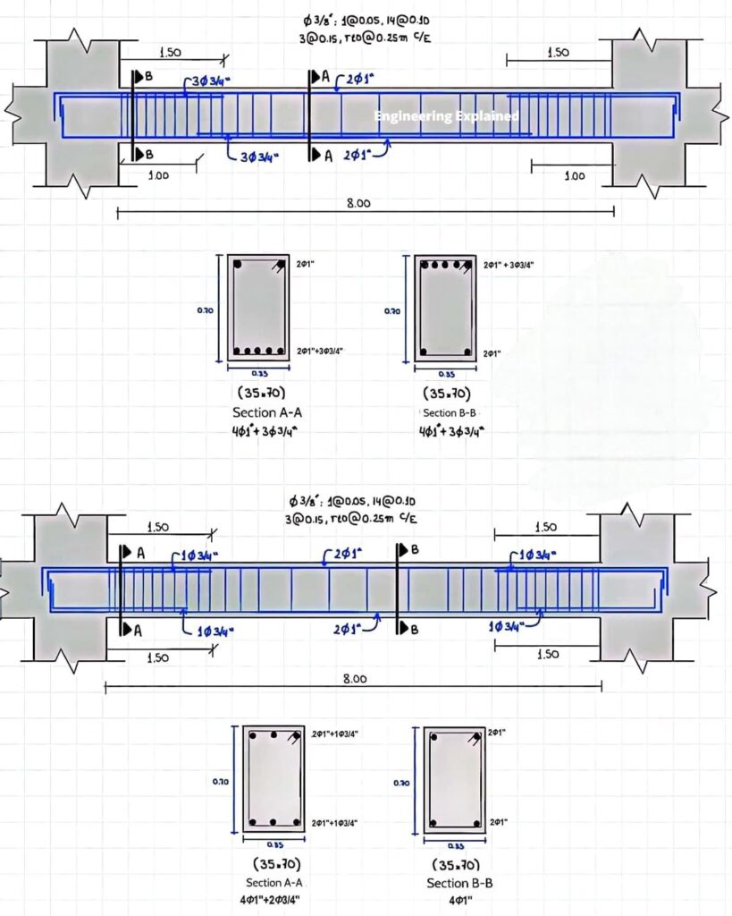
Let’s analyze the image you provided. While the specifics vary from project to project, the key elements are generally consistent.
- Overall Dimensions: The drawing shows the beam’s length (8.00 meters in the main span, with extensions of 1.50m on either side into the supports) and cross-sectional dimensions (0.30m tall, 0.35m wide). These dictate the beam’s load-carrying capacity and stiffness.
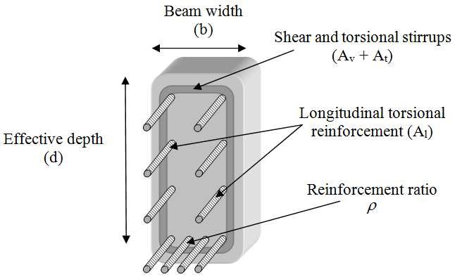
- Longitudinal Reinforcement (Main Bars): These bars run along the length of the beam and are primarily responsible for resisting bending forces (tension). In the drawing, we see variations in the number and size of these bars at different sections (A-A and B-B). For example, Section A-A shows “4Φ1″+2Φ3/4” or “4Φ1″+3Φ3/4″”, indicating four main bars of 1-inch diameter plus either two or three additional bars of 3/4-inch diameter. The placement is critical; these bars are typically concentrated near the bottom of the beam where tensile stresses are highest.
- Shear Reinforcement (Stirrups): The notation “Φ3/8”: 1@0.05, 14@0.10 3@0.15, rto@0.25m C/E” describes the stirrups, which are small, typically U-shaped bars that wrap around the longitudinal reinforcement. They resist shear forces, which are greatest near the supports. This notation can be interpreted as:
- “Φ3/8”: Use 3/8 inch diameter bars for the stirrups.
- “1@0.05”: Place 1 stirrup at 0.05 meter spacing.
- “14@0.10”: Place 14 stirrups at 0.10 meter spacing.
- “3@0.15, rto@0.25m C/E”: Place 3 stirrups at 0.15 meter spacing and then run other stirrups with 0.25 meter center-to-center spacing (C/E means center to each).
- Sections A-A and B-B: These are cross-sectional views taken at specific points along the beam’s length. They clearly show the arrangement and number of longitudinal and shear reinforcement bars within the concrete section. This enables to verify that reinforcement bars are placed in correct position and in correct numbers.
- Cover: The drawing implicitly indicates concrete cover – the distance between the outermost surface of the steel reinforcement and the face of the concrete. Adequate cover is vital to protect the steel from corrosion and fire.
Key Design Considerations
Designing an RC beam involves several crucial steps:
- Load Analysis: Determine the loads the beam will be subjected to (dead loads, live loads, wind loads, etc.).
- Bending Moment and Shear Force Diagrams: Create diagrams to visualize how bending moments and shear forces vary along the beam’s length.
- Flexural Design (Bending): Select the appropriate size and placement of longitudinal reinforcement to resist the bending moments. This involves calculations based on concrete strength (f’c), steel yield strength (fy), and safety factors.
- Shear Design: Determine the necessary size and spacing of stirrups to resist shear forces.
- Deflection Check: Ensure the beam’s deflection under load is within acceptable limits to prevent serviceability problems.
- Bond and Anchorage: Verify that the steel reinforcement is adequately bonded to the concrete to transfer stresses effectively.
- Detailing: Prepare detailed drawings that clearly show the placement of all reinforcement, including bends, laps, and splices. Proper detailing is essential for accurate construction.
Factors Influencing Beam Design
- Material Properties: The compressive strength of concrete (f’c) and the yield strength of steel (fy) are fundamental inputs.
- Span Length: Longer spans require larger beams and/or more reinforcement.
- Loading Conditions: Heavier loads demand stronger beams.
- Code Requirements: Building codes (e.g., ACI, Eurocode) specify minimum requirements for design, materials, and construction practices.
Moving Beyond the Basics
- Prestressed Concrete: Pre-tensioning or post-tensioning steel before or after concrete placement can significantly increase the beam’s load-carrying capacity.
- Composite Beams: Combining concrete with other materials, such as steel girders, can create highly efficient structural systems.
- Software Tools: Specialized software packages can streamline the design process, performing complex calculations and generating detailed drawings.
Recommendation
“Reinforced Concrete: Mechanics and Design,” by James Wight and James MacGregor. This book is a comprehensive resource, well-regarded by both students and practicing engineers. It covers the fundamental principles of reinforced concrete design, provides numerous examples, and reflects current code requirements. This book is very helpful.
Conclusion
Designing reinforced concrete beams is a multifaceted process that requires a thorough understanding of structural mechanics, material properties, and code regulations. While this post provides a basic overview, further study and practical experience are essential for mastering this crucial aspect of civil engineering.
Disclaimer: This blog post provides general information and should not be used as a substitute for professional engineering advice. Always consult with a qualified engineer for specific design requirements.

