Combined footings are a vital solution when dealing with closely spaced columns or columns located near property lines, where individual footings would overlap or be impractical. This post provides a deep dive into combined footing design principles, methodologies, and considerations for the practicing structural engineer.
Why Use a Combined Footing?
- Overlapping Footings: When individual column footings would overlap due to close column spacing.
- Proximity to Property Line: When a column is located very close to a property line, preventing a symmetrically loaded isolated footing.
- Unequal Column Loads: When one column carries a significantly larger load than an adjacent column.
- Low Soil Bearing Capacity: In some cases, a combined footing may provide a larger bearing area to satisfy soil bearing capacity requirements.
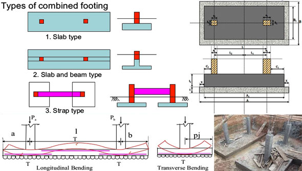
Types of Combined Footings:
- Rectangular Combined Footing: The most common type, typically used when columns carry approximately equal loads. The goal is to position the resultant of the column loads at the centroid of the footing area, ensuring uniform soil pressure.
- Trapezoidal Combined Footing: Used when columns carry significantly unequal loads. The trapezoidal shape helps to center the resultant load at the centroid of the footing area, minimizing eccentric loading.
- Strap Footing (Cantilever Footing): Consists of two individual footings connected by a rigid beam (the strap). The strap distributes the load from the eccentrically loaded footing to the other footing. A good option when rectangular or trapezoidal combined footings become excessively long.
Key Design Considerations:
- Soil Bearing Capacity (SBC): The foundation of the design. Obtain from the geotechnical report.
- Column Loads: Accurate determination of column loads (axial loads and moments) is crucial. Consider all relevant load combinations per your building code.
- Footing Geometry (Size and Shape): This is an iterative process aimed at achieving uniform soil pressure.
- Location of Resultant Force: Calculate the location of the resultant force (R) of all column loads acting on the footing.
- Centroid of Footing: The goal is to design the footing such that the centroid of the footing area coincides with the location of the resultant force (R). This minimizes eccentricity and promotes uniform soil pressure.
- Rectangular Footing: Determine the required length (L) and width (B) of the footing to achieve the desired centroid location and satisfy the area requirement (Af = (Sum of column loads) / SBC).
- Trapezoidal Footing: Determine the required lengths of the two parallel sides (a and b) and the width (B) of the footing to achieve the desired centroid location and satisfy the area requirement. The formula for the centroid of a trapezoid will be needed.
- Overhang: Provide adequate overhang beyond the column faces.
- Soil Pressure Distribution:
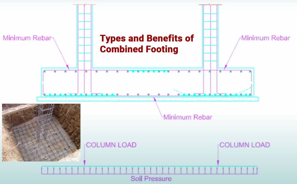
- Uniform Soil Pressure: Strive for uniform soil pressure by centering the resultant force. Calculate the net soil pressure (qnet = (Sum of column loads) / Footing area).
- Eccentricity: If eccentricity exists (resultant force not at the centroid), calculate the maximum and minimum soil pressures using the formula: qmax/min = (Sum of column loads) / Footing area +/- (Mxy)/Ix +/- (Myx)/Iy, where Mx and My are moments about the centroidal axes, and Ix and Iy are the moments of inertia of the footing area. Ensure that qmax does not exceed the allowable SBC.
- Bending Moment and Shear Force Diagrams: Develop accurate bending moment and shear force diagrams along both the longitudinal and transverse axes of the footing.
- Longitudinal Direction: The footing acts as an inverted beam subjected to the upward soil pressure and the downward column loads.
- Transverse Direction: The footing acts as a cantilever beam extending from the column face in the transverse direction.
- Footing Depth: Determined by bending and shear requirements.
- Bending: Calculate the maximum bending moments at critical sections (e.g., under the columns, at points of zero shear). Determine the required effective depth (d) based on the maximum bending moment, material properties, and code-specified reinforcement ratios.
- One-Way Shear: Check one-way shear (beam shear) at a distance ‘d’ from the column face.
- Two-Way Shear (Punching Shear): Check two-way shear (punching shear) around each column. This is often the controlling factor for footing depth, especially for heavily loaded columns.
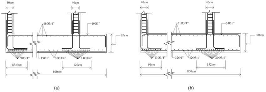
- Reinforcement Design:
- Longitudinal Reinforcement: Design longitudinal reinforcement to resist the bending moments along the length of the footing. Provide top reinforcement in regions of negative bending moment and bottom reinforcement in regions of positive bending moment.
- Transverse Reinforcement: Design transverse reinforcement to resist the bending moments in the transverse direction.
- Minimum Reinforcement: Meet minimum reinforcement requirements as per your building code.
- Distribution: Properly distribute the reinforcement to control cracking.
- Shear Reinforcement (If Required): If the concrete shear capacity is insufficient, provide shear reinforcement in the form of stirrups. Shear reinforcement is more likely to be needed in heavily loaded combined footings.
- Transfer of Force at Column Base: Similar to isolated footings, check bearing stress at the column-footing interface and design dowels if needed.
- Code Compliance: Adhere to ACI 318, Eurocode 2, IS 456, or the relevant local building code.
Design Process:
- Gather Information: Geotechnical report (SBC), column loads, column locations, property line location (if applicable), and governing building code.
- Determine Footing Type: Select the appropriate footing type (rectangular, trapezoidal, or strap) based on column loads and spacing.
- Size and Shape the Footing: Determine the dimensions of the footing to achieve uniform soil pressure (or minimize eccentricity).
- Calculate Soil Pressure: Calculate the net soil pressure distribution.
- Develop Bending Moment and Shear Force Diagrams: Develop BM and SF diagrams along both the longitudinal and transverse axes.
- Determine Footing Depth: Determine the required footing depth based on bending and shear requirements.
- Design Reinforcement: Design longitudinal and transverse reinforcement.
- Check Shear Reinforcement: Check if shear reinforcement is required.
- Check Bearing Stress: Verify bearing stress at the column-footing interface and design dowels if needed.
- Detailing: Prepare detailed reinforcement drawings.
Software and Tools:
- Structural Analysis Software: ETABS, SAFE, RISAFoundation.
- Spreadsheet Software: Crucial for performing iterative calculations for footing size, soil pressure, and reinforcement design.
- CAD Software: For creating detailed reinforcement drawings.
Common Mistakes to Avoid:
- Inaccurate Load Determination: Leads to incorrect footing size and reinforcement design.
- Ignoring Eccentricity: Can lead to uneven soil pressure and potential overturning.
- Inadequate Shear Design: A common failure point.
- Incorrect Bending Moment and Shear Force Diagrams: Result in incorrect reinforcement design.
- Insufficient Development Length: Leads to bond failure.
- Ignoring Code Requirements: Compromises safety and structural integrity.
Recommended Reading:
- “Reinforced Concrete: Mechanics and Design” by James K. Wight. Good coverage of combined footings.
- “Design of Reinforced Concrete Structures” by Jack C. McCormac and Russell H. Brown. Another reliable textbook with detailed explanations.
- “Structural Concrete: Theory and Design” by M. Nadim Hassoun and Akthem Al-Manaseer. More advanced coverage.
- ACI 318 “Building Code Requirements for Structural Concrete” Mandatory
Conclusion:
Combined footing design requires a thorough understanding of structural mechanics, soil behavior, and relevant building codes. By following a systematic approach, carefully considering all relevant factors, and utilizing appropriate tools, you can design safe and efficient combined footings that effectively support your structures. Remember to double-check your calculations and always consult with experienced engineers when needed.

